![]()
|
|
|
|
Basic Technology of Quartz Crystal ResonatorsQuartz crystal resonators (often called “crystals”) are widely used in frequency control applications because of their unequalled combination of high Q, stability, small size and low cost. Many different substances have been investigated as possible resonator materials, but for many years quartz resonators have been preferred in satisfying needs for precise frequency control. Compared to other resonators, for example, LC circuits, mechanical resonators such as tuning forks, and piezoelectric ceramic resonators based or other single-crystal materials, the quartz resonator has a unique combination of properties. First, the material properties of single-crystal quartz are extremely stable with time, temperature, and other environmental changes, as well as highly repeatable from one specimen to another. The acoustic loss or internal friction of quartz is very low, leading directly to one of the key properties of a quartz resonator, its extremely high Q factor. The intrinsic Q of quartz is about 107 at 1 MHz. Mounted resonators typically have Q factors ranging from tens of thousands to several hundred thousand, which is orders of magnitude better than the best LC circuits. The second key property of the quartz resonator is its stability with respect to temperature variation. Depending on the shape and orientation of the crystal blank, many different modes of vibration can be used and it is possible to control the frequency-temperature characteristics of the quartz resonator to within close limits by an appropriate choice. The most commonly used type of resonator is the AT-cut, where the quartz blank is in the form of thin plate cut as an angle of about 35°15' to the optic axis of the crystal. The third essential characteristic of the quartz resonator is related to the stability of its mechanical properties. Short and long term stabilities manifested in frequency drifts of only a few parts per million per year are readily available from commercial units. Precision crystal units manufactured under closely controlled conditions are second only to atomic clocks in the frequency stability and precision achieved. Quartz Plate Orientation Quartz resonators consist of suitably mounted and metal-deposited plates of
crystalline quartz using bulk acoustic wave (BAW) vibrations. Originally the quartz plates were made from natural quartz, but today
cultured quartz is used almost exclusively. The plates (also called wafers or blanks) are fabricated at a precise
orientation with respect to the crystallographic axes of the quartz material.
The orientation or "cut" determines frequency-temperature characteristics and other important properties of the resonator.
The above is a schematic diagram of a cultured quartz crystal grown from a Y-oriented seed crystal for use in fabricating AT-cut resonators. A seed crystal establishes the initial crystal orientation and encourages growth in the Y direction at the expense of the Z-axis. Seed crystals are carefully selected to avoid defects which might propagate as the crystal grows. The position of the seed crystal is indicated. The lines sloping left from the x-axis mark the saw cut position for AT plates, the line sloping to the right indicates the BT-cut. In practice, these angles are very critical and are precisely determined using Bragg x-ray diffraction. Vibration ModesThe quartz plate, like all plates, has many modes of vibration. There are three basic modes of vibration as illustrated in the following figure.
(a) Flexure mode (bending or bowing); Cuts: 5° X, NT; Frequency ~ 100 kHz. (b) Extensional Mode (displacement along the length of the plate); Cuts: MT, GT; Frequency: 40 – 200 kHz. (c) Shear Mode (sliding two parallel planes in opposite directions). This mode is subdivided into: Face Shear; Cuts: CT, DT; Frequency: 100 – 600 kHz. Thickness Shear; Cuts: AT, BT, SC; Frequency: 1 – 30 MHz (fundamental mode); 30 – 90 MHz (3rd harmonic overtone mode); 60 – 150 MHz (5th harmonic overtone mode); etc. Properly oriented electrodes excite the desired mode of vibration. Although a large number of different cuts have been developed, some are used only at low frequency, others are used in applications other than frequency control, and still others have been made obsolete by later developments. Except for the low-frequency tuning fork resonators used in quartz watches and clocks, almost all quartz resonators in today’s applications use a thickness-shear mode. At frequency above approximately 1 MHz, AT-cut and SC-cut are primarily used. For frequencies below about 1 MHz, thickness-mode resonators generally become impractical because of size, since the blank diameter must be much greater than the thickness. AT- and SC- cut Resonator FrequencyThe fundamental frequency of a thickness-shear resonator is inversely proportional to its thickness. The thinner the crystal blank, the higher the frequency. There are additional resonance at the 3rd, 5th, etc. harmonic overtones, whose frequencies are approximate, but not exact, odd multiples of the fundamental resonance frequency. Resonators are ordinarily designed to optimize the characteristics of one or another of these resonances, such as the fundamental or the third overtone, but the other overtones necessarily still exist. AT-cuts are commonly manufactured in the frequency range from 1 MHz to 250 MHz and above, and in this range are usually the optimum choices for most applications. However, the AT-cut is sensitive to stresses in the body of the resonator, whether caused by temperature gradients due to rapid external temperature changes, or by external forces. For applications where extreme stability is required, this stress sensitivity is a drawback, and newer crystal cuts such as the SC (Stress Compensated)-cut have been developed that minimize these effects. An SC-cut crystal is one of a family of double rotated crystals (quartz crystals cut on an angle relative to two of the three crystallographic axes). Others in the family include the IT-cut and FC-cut. The SC-cut represents the optimum double rotated design as its particular angle ~ 35°15 ø ~ 21°54 provides maximum stress compensation. The SC-cut is also a thickness mode resonator, and as such is basically available in much the same frequency range as the AT-cut, but its commercial availability is much more limited due to difficult manufacturing process.
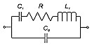
Equivalent CircuitA quartz crystal resonator is a mechanically vibrating system that is linked, via the piezoelectric effect, to the electrical world. It consists of a quartz plate with metal plating (electrodes), which is located on both sides of the quartz plate and is connected to insulated leads on the crystal package. Although the theoretical analysis of this device is a relatively complex electro-mechanical function, it can be expressed in terms of a simple equivalent circuit in the vicinity of the resonance frequencies as shown below:
Equivalent electric circuit of quartz crystal resonator The C0, called the “shunt” or static capacitance, is the capacitance due to the electrodes on the crystal plate plus the stray capacitances due to the crystal enclosure. Shunt capacitance is present whether the crystal plate is oscillating or not (unrelated to the piezoelectric effect of the quartz). The R, C1 and L1 portion of the circuit is known as the “motional arm”, which arises from the mechanical vibrations of the crystal. R represents the equivalent motional arm resistance; C1 represents the motional capacitance of the quartz; and L1 is the motional inductance, a function of the mass. The C0 to C1 ratio is a measure of the interconversion between electrical and mechanical energy stored in the crystal, i.e., of the piezoelectric coupling factor, k. C0/C1 increases with the square of the overtone number. When a dc voltage is applied to the electrodes of a resonator, the capacitance ratio C0/C1 is also a measure of the ratio of electrical energy stored in the capacitor formed by the electrodes to the energy stored elastically in the crystal due to the lattice strains produced by the piezoelectric effect. When working with most crystal resonators, it is only necessary to specify one motional component or the other due to the absolute correlation between C1 and L1 (C1*L1 is constant for a given series resonant frequency). The industry standard is to specify a proper value of C1 only. The actual value of C1 has physical limitations when it is realized in a quartz crystal design. These constraints include the quartz cut, the mechanical design, the mode of operation and the nominal frequency of the crystal resonator. Although the equivalent circuit appears relatively simple, determining the several characteristic frequencies useful in describing resonator equivalent circuit properties is surprisingly complex. For the most part, simple approximations are used. The following notation is useful in determining some of these frequencies. Fs (Series resonance frequency) = 1 / [2p(L1C1)1/2] Fp (Parallel Resonance frequency) = fs[1 + 1/(2g)] g (Capacitance ratio) = 2pfsC0 / C1 Q (Quality factor) = 2pfsL1 / R1 M (Figure of merit) = Q / g Series vs. Parallel ResonanceThe frequency at which oscillation occurs defined by fs is called Series Resonance Frequency. The reactance/impedance curve of a crystal shown below reveals where mechanical resonance occurs.
Series resonance occurs at the point the curve crosses zero. At this point, the crystal appears resistive in the circuit, impedance is at minimum and current flow is at maximum. As the frequency is increased beyond the point of series resonance, the crystal appears inductive in the circuit. When the reactance of the motional inductance and shunt capacitance cancel, the crystal is at the frequency called Anti-resonance Frequency denoted as (fp). At this point, impedance is maximized and the current flow is minimized. The frequency of a crystal at fp is inherently unstable and should be never selected as the frequency of operation for an oscillator. The region between fs and fp is typically called “Area of Parallel Resonance”. Parallel resonance can occur by adding load capacitance to the crystal in series resulting a positive frequency shift determined by: Df = fsC1/2(C0 + CL) The unavoidable presence of Co in the equivalent circuit produces this anti-resonance, sometimes also called parallel resonance. In this connection, r = C0/C1 is an important resonator parameter because it is inversely proportional to the spacing between resonance and antiresonance and thereby determines the maximum bandwidth in filters and the tuning range in oscillators. OvertonesQuartz crystals naturally vibrate in several simultaneous resonance modes referred to the fundamental or overtone modes. Usually, one of these modes is designed to be dominant at the desired operating frequency. The fundamental frequency of vibration is a function of the resonator physical dimension and angle of cut. The overtone modes occur at odd numbered harmonics of the fundamental mode and include the 3rd, 5th, 7th, 9th, and 11th. The maximum bandwidth obtainable in a filter and the maximum tuning range in an oscillator are inversely proportional to the capacitance ratio, r = Co/C1, and r increases as the square of the overtone. Consequently, a wider bandwidth or larger tuning range can be obtained with a fundamental mode resonator than with a third or higher overtones. Fundamental mode resonators are used for most filters, temperature compensated oscillators (TCXOs) and voltage controlled oscillators (VCXOs), where the required bandwidth or tuning range makes overtone devices undesirable. Fundamentals are also used in many simple oscillators, such as clock oscillators at frequencies up to approximately 35 MHz. At higher frequencies overtones are more economical for this application. Current crystal manufacturing processes limit the lapping of the quartz plate so that the highest fundamental mode frequency that may be reliably achieved is typically around 45 MHz. At this frequency, the AT-cut quartz plate is less than 0.037 mm thick and further lapping using conventional techniques is not practical. Several methods have been developed to increase the fundamental mode frequency achievable by removing some quartz mass from the center of the plate. This so-called “inverted mesa” provides for an active area that is much thinner and is usually achieved by chemical or plasma/ion etching. These processes can produce superior quality high frequency fundamental (HFF) mode crystal to 170 MHz and beyond. Fundamental mode crystals typically have larger values of C1 than overtone mode crystals of the same frequency; therefore they are useful for applications such as VCXOs where greater pullability is required. High frequency fundamental quartz blanks are also used extensively in filter applications where they provide better spurious mode response than overtone crystals of the same frequency. At a given operating frequency, quartz crystals aging and Q improve with higher overtone. For this reason, ovenized oscillators (OCXOs) often use overtone resonators. Usually the 3rd or 5th overtone is used. The range of tuning required to accommodate the resonator frequency tolerance and aging characteristics limits the maximum useful overtone. Spurious ModesVibration at frequencies that are not fundamental or overtone modes are referred to as spurious or unwanted modes. The design of the wafer, electrode pattern and amount of metalization can be adjusted to suppress these unwanted modes.
Spurious modes can be a problem if the response is as strong as the main mode. When that happens, the oscillator may run on the spur instead of the main mode. This is called mode hopping. Spurious modes should be specified as either a resistance ratio to the main mode or dB suppression. In general, a resistance ratio of 1.5 or 2.0 to 1, which is approximately equivalent to – 3 dB to –6 dB, is sufficient to avoid mode hopping for most oscillators. Fundamental modes of a crystal can achieve the best spurious suppression, while overtone responses are more difficult to control. Designs that require higher C1 volumes for pullability reasons also can sacrifice spurious mode suppression. For crystal filter applications, spurious mode suppression as low as –40 dB can be achieved with fundamental mode with low C1 designs. The spurious modes occur above the main mode within a few hundred kilohertz. The response may look like the plot shown above. In oscillator applications, the oscillator usually selects the strongest mode. Some of the unwanted modes may have steep frequency vs. temperature characteristics. Occasionally, as the temperature changes, at a certain temperature, the frequency of an unwanted mode coincides with the oscillator frequency, which causes so-called “activity dip”. At the activity dip, excitation of the unwanted mode results in extra energy dissipation in the resonator, which results in a decrease in the Q, an increase in the equivalent series resistance, and a change in the frequency of the oscillator. When the resistance increase is sufficiently large, the oscillation may stop, i.e., the oscillator fails. When the temperature changes away from the activity dip temperature, the oscillation can restart. Unwanted modes can be controlled by proper design and fabrication methods. Maintaining the correct relationships among electrode and resonator plate dimensions (i.e., applying energy trapping rules), and maintaining the parallelism between the major faces of the resonator plate, can minimize the unwanted modes. Frequency-Temperature CharacteristicsThe frequency-temperature characteristic defines how the resonant frequency of the quartz crystal resonator varies in response to changes in temperature. For both AT- and SC-cut resonators, it is found that the frequency shift due to the variation of temperature can be expressed in a cubic curve of the form: Df/f0 = a0(T – T0) + b0(T – T0)2 + c0(T – T0)3 T is the temperature variable and T0 is the inflection temperature, which is approximately 25°C for the AT-cut and 92°C for the SC-cut. The coefficients a0, b0, and c0 are the first -, second-, and third order temperature coefficients of frequency, and they are constants that depend on quartz properties and the angle of cut. The above equation gives a family of curves as shown below for four values of the relative cut angle. These curves show that a resonator can be designed to give a relatively small frequency variation over a broad temperature range.
AT-cut Frequency vs. Temperature Curves
SC-cut Frequency vs. Temperature Curves Both cuts are useful for temperature controlled (ovenized) applications. In addition, since the AT-cut inflection temperature (To) is approximately 25°C, it is widely used for uncontrolled temperature applications such as filters and non-ovenized oscillators. Both cuts vibrate in thickness modes that can be designed to have very low mounting losses and hence provide exceptional Q (up to 1.5 x 10⁶ at 10 MHz and 35 x 10³ at 300 MHz) and stability with time (example 1 x 10⁻¹⁰/day at 10 MHz). Aging and DriftBased on the terms and definitions recommended by the CCIR (Consultative Committee on International Radio) , aging and drift can be defined in the following way. Aging is the systematic change in frequency with time due to internal changes in the oscillator, that is, the frequency change with time when factors external to the oscillator (environment, power supply, etc.) are kept constant. Drift is defined as the systematic change in frequency with time of an oscillator, that is, drift is due to a combination of factors, i.e., it due to aging plus changes in the environment and other factors external to the oscillator. Aging is what one specifies and what one measures during oscillator evaluation. Drift is what one observes in an application. For example, the drift of an oscillator in a spacecraft is due to (the algebraic sum of) aging and frequency changes due to radiation, temperature changes in the spacecraft, and power supply changes. There are many interrelated factors involved in aging. Some of the most common are: internal contamination, crystal surface changes, wire fatigue, small irreversible changes in the crystal lattice, out gassing of the materials, various thermal effects, mounting stresses, and over-driving the crystal. Typical aging figures for metal enclosure crystal units operating in the frequency range of 10 to 20 MHz are 1.0 – 5.0 ppm / 1st year; while the values for glass enclosure crystals are 0.1 – 1.0 ppm / 1st yesr. AT-cut vs. SC-cutOf many crystal-cut types available, most applications use either AT-cut or SC-cut quartz resonators, and in many instances both cuts are candidates. It is worthwhile to compare them on the basis of eight characteristics: Turnover Temperature For OCXO applications the crystal may be operated at either of its two
turnover temperatures. Here the
SC-cut is superior to the AT-cut in two important ways.
First, the SC-cut’s f - T curve is much flatter near turnover
temperature than the AT-cut’s determined by the three temperature
coefficients. Second, the true
SC-cut is much less sensitive to temperature gradients, allowing much faster
warm-up. These qualities make it
the preferred choice for precision oscillator applications. Static f - T Characteristic: Both AT- and SC-cut resonators have a static frequency-temperature characteristic that is well described by a third-order polynomial in temperature. For the AT-cut, the inflection temperature [at which the curvature changes sign] is within a few degrees of room temperature. In other words, the f - T curve is approximately anti-symmetric about a temperature close to 25°C. This makes the AT-cut suitable for non-temperature-controlled applications, such as simple oscillators and TCXOs. By contrast, the inflection temperature for the SC-cut resonator is 92°C. Most SC-cuts are used in OCXOs, where the higher inflection temperature results in an important advantage, that is, the f-T curve is quite flat in the vicinity of the oven set point, which is adjusted to the resonator upper or lower turnover temperature. Consequently, temperature control is less critical than that an AT-cut crystal was used. Other advantages of the SC-cut from its f – T characteristics are its relative freedom from the activity dips. Dynamic f-T Characteristic (Thermal Transient Effects): When a step change is made to the ambient temperature, the frequency of an SC-cut resonator changes smoothly, without overshoot or ringing, in a manner corresponding to a critically- damped system. The AT-cut dynamic f - T characteristics, on the other hand, has very pronounced overshoot and rubber band effect. An important reason for choosing an SC-cut for an OCXO is its greatly improved dynamics, which is, in fact, the hallmark of properly designed SC-cut based OCXOs. Aging: If we compare equal frequency and overtone, the SC-cut is slightly better than the AT-cut, on account of its slightly greater thickness. This difference, however, is usually insignificant. Because the greater current-handling capability of the SC renders its frequency less sensitive to current changes, in oscillators the SC-cut may exhibit better aging. Current Handling: This refers to the maximum current at which a resonator can be operated without a significant (reversible) change in frequency. Generally, this is markedly higher for SC-cut than for AT-cut resonators. The consequences for oscillator applications are an improved phase noise floor by operating a higher current, and reduced sensitivity to drive level change, which may affect aging of the oscillator frequency. Impedance Level: If we compare AT-cut and SC-cut resonators having the same frequency and overtone, the motional inductance (L1) and motional resistance (R) of the SC-cut resonator will be significantly higher than for the AT-cut resonator, while the motional capacitance (C1) will be lower in the same proportion. The static capacitance (C0), however, will be nearly the same for the two. For oscillator applications, high impedance is desirable if aging is important, because it reduces the effect of the sustaining circuit on the oscillator frequency. The trade-off is that high resonator impedance reduces the tuning range of the oscillator frequency, limiting corrections for manufacturing tolerance and for aging. In VCXOs, aging is, at most, a secondary consideration, so that the required tuning range will determine the highest practical overtone. For either cut, the impedance level increases roughly as the square of the overtone for a given frequency, but also depends upon details of the resonator design. Size: For most applications, the sizes of the AT-cut and SC-cut resonator packages are the same. Cost: Because of tighter orientation tolerances, the SC-cut is more expensive to manufacture than the AT-cut, but for high-performance applications this cost is more than offset by savings in oven complexity, and for many applications the SC-cut is the only choice. For some applications where thermal transient characteristics are less important, a modified (near) SC-cut may be used. This provides essentially the same f - T curve as the true SC-cut but allows looser orientation tolerances, thereby providing some cost savings at the expense of thermal transient performance. Normally, cuts having To much removed from 92°C will not provide the thermal transient performance for which the true SC-cut is noted. Quartz Turning Folk Resonators / Watch CrystalThe requirements of quartz resonators for wristwatch are: small size, low power dissipation (including the oscillator), low cost, and high stability (temperature, aging, shock, attitude). These requirements can be met with 32.768 kHz quartz turning fork resonators. It is interesting to know that 32768 = 215 or 1 Hz = 32768/215. In an analog watch, a stepping motor receives one impulse per second which advances the second pin by 6, i.e., 1/60th of a circle every second. The 32.768 kHz is a compromise among size, power requirement (i.e., batter life) and stability. Quartz wristwatches are sufficiently accurate, usually, while worn as intended, i.e., on the wrist for ~16 h and off the wrist for ~8 h each day. The accuracies degrade when the watch is off the wrist for extended periods. The further the storage temperature is from the optimum temperature, the faster the watch loses time. At temperature extremes, e.g., in a freezer at - 55°C, or at the temperature of boiling water, wristwatches lose about 20 s per day. The angle of cut of the resonator used in wristwatches is such that the zero temperature coefficient is at ~ 25°C, as shown in the following f – T curve. This has been found to provide the highest probability of accuracy, based on the typical durations and temperatures while the watch is on the wrist and while it is off the wrist. Type of Seal for Quartz Crystal ResonatorsSolder Seal Solder seal packages have several advantages. They have lower lead-to-case capacitance than other types and therefore used in some filter designs that require minimal junction capacitance. In addition, the packages can be opened for rework that is sometimes helpful in meeting difficult filter requirements. Their main disadvantage is that they cannot be sealed without introducing contamination, and therefore they tend to have relatively poor frequency stability. Resistance Weld These packages require more sophisticated sealing equipment than solder seal, but the sealing process introduces less contamination, resulting in better frequency stability. Resistance weld packages are available in a wide range of styles, and all are economical choices for long-term performance Seam Weld Seam weld sealing is the most widely used method today in producing ceramic base/metal cover low profile SMD crystals and oscillators. Performance and cost are similar to those resistance weld packages. Epoxy Seal Epoxy seal packages are widely used for high volume and low cost SMD crystals. The frequency stability performance is not as good as those seam weld and resistance weld parts. Cold Weld Cold weld sealing is a precision performance package that is somewhat more expensive, but sealing process introduces virtually no contamination, resulting in superior resonator frequency stability and electrical performance. All-Quartz Package An all-quartz packaging technique is used in producing a surface mount resonator having very low profile and very high shock resistance. The availability of this type of sealing package is rather limited. Detailed Frequency Temperature Curve for Fundamental Mode "AT-cut" Crystals
The above curves represent the frequency vs. temperature characteristics of a series of AT-cut crystals. Each numbered curve is accomplished by controlling the angle of the crystal cut in reference to the angle (35° 15' ) and each curve is one minute of change. LTP indicates the Lower Temperature Turnover Point; while UTP indicates the Upper Temperature Turnover Point. |