![]()
|
|
|
|
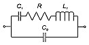
Ceramic ResonatorsCeramic Resonators vs. Crystal Resonators: Ceramic resonators stand between quartz crystal resonators and LC/RC resonators in regard to accuracy. They are considerably smaller; require no adjustments, with improved start-up time and low in cost. In lower-frequency applications where moderate stability can be used and where cost is an overriding consideration; ceramic resonators are often the choice over quartz crystal resonators. Properties: Ceramic resonators are made of polycrystalline ferroelectric materials in the barium titanate and zirconate families. The ceramic mixture is formed to its desired shape and converted to an artificial piezoelectric by slow cooling from a temperature above the ferroelectric transition point in the presence of a strong electric field. In a manner analogous to the formation of a magnet by aligning molecular dipoles in a strong field, the molecular electric dipoles are oriented. When the high voltage is disconnected from the cooled sample, the preferential orientations of the electric dipoles of the polycrystalline aggregate yield a permanent electric moment, which is equivalent to the presence of piezoelectricity. Equivalent Circuit: The equivalent electric circuit of a ceramic resonator is similar to the quartz crystal resonator’s equivalent circuit, i.e., consists of a series L1, C1, R circuit shunting with a parallel C0 capacitance as shown in the following:
Frequency Range: For ordinary applications the frequency range of ceramic resonators ranges from tens of kHz to about 50 MHz. Frequency Stability: The maximum allowable frequency deviation compared to the measured frequency at 25° C over the temperature range, i.e., -20° C to +80° C. The typical stability for ceramic resonators is ± 0.3% (± 3000 ppm). Frequency Tolerance: The allowable deviation from the nominal frequency at room temperature. The typical frequency tolerance for ceramic resonators is ±0.5% (± 5000 ppm). Resonant Impedance: The value of impedance the resonator exhibits in the operating circuit. Aging: The relative frequency change over a certain period of time. This rate of change in frequency is normally exponential in character. The typical aging for ceramic resonators is ± 0.5% (± 5000 ppm) over 10 years. Load Capacitance: Load capacitance (CL) is the amount of capacitance that the oscillator exhibits when looking into the circuit through the two resonator terminals. Load capacitance is expressed in a pair of external capacitance C1 and C2 with the default values given in the specification. Filter Applications: Because of the high coupling values that may be obtained (low C0/C1 values), ceramic resonators are suitable for medium and wideband low-loss filters. One drawback of these resonators is their temperature coefficient of frequency, which is large, being in the range of –40 to –80 ppm per °C. For wideband applications this is not a severe limitation, but for narrowband oscillator application temperature regulation or compensation would more than cancel any cost savings of the element over a corresponding quartz crystal resonator. |